CNC: System Setup
1. CNC Structure
2. Requirements for PC and MINI-PC
3. Image Installation for EtherCat Driver
4. Starting Setup
5. EtherCat Setup
6. Machine Axis Setup
7. ModBus Setup
8. Linking Inputs-Outputs to PLC
9. PLC Settings
10. Machine System Setup
1. General Machine Systems
2. Spindle control settings
3. Probe, Tool Sensors
4. Cooling System
5. MQL System
6. Lubrication System
7. Other Systems
11. Setting Reference Coordinates
12. Setting Machine NC Cycles
13. Correcting Machine Geometry
14. Adding G and M Commands
1. CNC Structure
Recommended CNC connection scheme to the EtherCat system:

Features of the option:
• A separate MINI-PC is used for the EtherCat driver.
• Linux (without a graphical shell) with a RealTime (RT) system must be installed on this MINI-PC.
• On the main PC, it is possible to work both under Windows and under Linux.
• Work with ModBus via RS 485 is possible both from the main PC, from the MINI-PC, and from Beckhoff EL2061.
• This scheme is especially recommended for working with a cycle of less than 1ms.
• Also, with this scheme, the requirements for the main PC are much lower.
CNC connection scheme to the EtherCat system using one PC:

Features of the option:
• One PC is used.
• Only Linux with a RealTime (RT) system must be installed on this PC.
• Work with ModBus via RS 485 is possible both from the PC and from Beckhoff EL2061.
• This scheme is not recommended for working with a cycle of less than 1ms.
2. Requirements for PC and MINI-PC
Requirements for PC (in case of working with MINI-PC as a driver):
• Processor: x64 or ARM64
• OS: Windows / Linux
• RAM: min 8GB / preferably 16GB
• Monitor: Touchscreen
• Ethetnet Ports: 1 port will be occupied for communication with MINI-PC
MINI-PC (or to the main PC in case of working on one PC)
• Processor: x64 or ARM64
• OS: Linux
- Installing a graphical shell is not necessary (and harmful)
• Real-time system Preempt-RT
• RAM: 1GB
• Ethetnet Ports: 2 ports are required
- Installation and configuration of Linux, installation of the RT kernel is completely the same as LinuxCNC:
Debian Bookworm Installation (with Preempt-RT kernel)
3. Image Installation for EtherCat Driver
To facilitate system installation, two images have been prepared for the most common cheap MINI-PCs
NanoPi R5C

T9 PLUS

Download page for distributions
4. Starting Setup
First you need to load the initial CNC settings.
Go to "Settings" -> "Archive":

On the right panel, select the group "Regular CNC delivery" -> "1_Start_1-Chanel.zip"
On the left panel, select all items (press the "Select all" button)
Click on the "Load archive" button on the sidebar
Reboot the CNC.
Go to settings (Button at the bottom "Settings", then the button on the right "Parameters").

Select the group "CNC interface settings".
You should pay attention to the following settings:
• Interface language - Select the desired localization language
• CNC screen theme - Select the desired theme - dark or light
• Full screen window - As a rule, you need to expand the CNC window to the entire screen
• Screen scale - For Linux, you need to select the interface scaling on the screen
(Requires CNC reboot)
Select the group "General CNC settings".
Specify the name of your machine:
• Machine model name
(This will help with archiving and restoring settings)
5. EtherCat Setup
Go to "Settings", then the button on the right "Parameters".

Select the group "EtherCat settings".
In the "Driver type" field - Select where the driver will be launched:
• Current PC - The driver will run on the local machine.
- Only for Linux with RT installed
SSH must be configured on the local PC with startup from root
• Remote PC - The driver will run on the remote PC.
- SSH must be configured on the remote PC with startup from root
- If "Remote PC" is selected, then specify the IP of this PC.
- If you are using a Linux image for a remote PC from our website - then:
- IP: "192.168.211.2"
Specify the login and password from SSH
• SSH: User login
• SSH: User password
- If you are using a Linux image for a remote PC from our website - then:
- Login "cnc" Password "12"
Save the settings and reboot the CNC.
Go to settings again (Button at the bottom "Settings", then the button on the right "Parameters").
Select the group "EtherCat settings".
Specify the Ethernet interface - through which the exchange with EtherCat devices will take place.
• EtherCat network interface name
- Set the servo cycle start frequency to the standard one for the beginning - 1ms
• Servo cycle start frequency
Save the settings and reboot the CNC.
Go to "Settings", then the button on the right "EtherCat").
If everything is connected correctly, the CNC should have seen and read all EtherCat devices
Next, you need to load the ESI file (EtherCat device description)
Select the desired device, and click on the "Load ESI" button on the sidebar:

If there is an ESI file for your device on the JupiterCNC website:
the system will prompt you to select the file version
Click the "Load ESI" button in the window
This must be done for all different types of devices.
If there is no ESI file for your device on the website
- request or download it from the website of the manufacturer of this EtherCat device
Later - after rebooting - you can click on the "Upload ESI" button on the sidebar
- this will allow other users to easily get the ESI file.
- if the file is not standard (for example, you added a description or translation of settings), then when unloading you can specify a note to the file
Save the settings and reboot the CNC.
Go to "Settings" again, then the button on the right "EtherCat").
It is necessary to set some EtherCat device settings:
For Input-Output devices:
For the desired PDO, set the Input-Output type:
• Discrete Input-Output
• Analog (numeric) Input-Output

For correct installation, read the documentation of the EtherCat device manufacturer
You can also apply a signal to the device input - and understand what to specify by the changed value of the PDO.
For Servo-Driver devices:
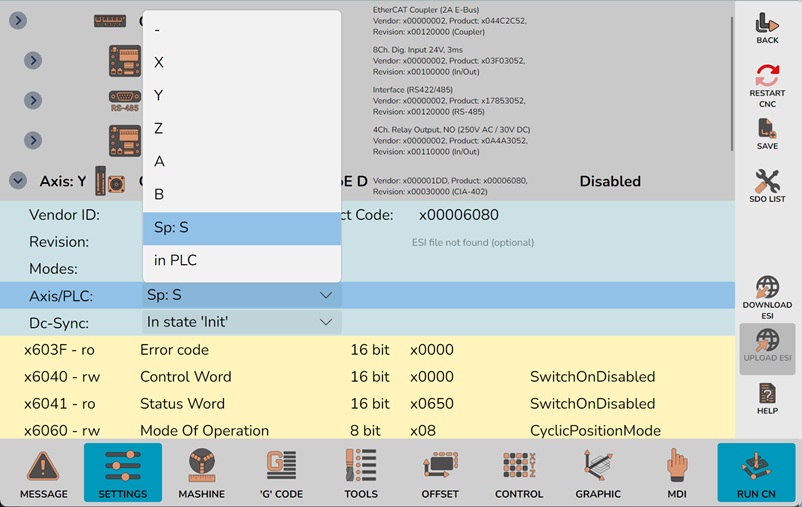
1. Set the axis letter of the drive
2. Set the status in which the CNC will program DC-Sync
- As a rule, you need to select "In state 'Init'"
3. For the desired PDO, set the Input-Output type (exactly the same as for Input-Output devices):
• Discrete Input-Output
• Analog (numeric) Input-Output

For correct installation, read the documentation of the EtherCat device manufacturer
You can also apply a signal to the device input - and understand what to specify by the changed value of the PDO.
Not all Servo-Drivers have Inputs and Outputs.
Also, some outputs may be virtual and are intended to control the drive itself.
ATTENTION!
Inputs and outputs in Servo-Driver are usually very delicate in terms of load - they are very easy to burn.
6. Machine Axis Setup
Go to "Settings", then the button on the right "Parameters".
Select the group "Machine axis settings".

All possible axes have been added in the starting settings: XYZABC
Delete unnecessary axes using the "-" button after the axis name.
Next, we check the parameters:
• Position on the screen
- Placing information about the axis on the CNC screen
- If "Position #1/2/3.." - then a whole line will be allocated for the axis
- If "Pos 1, Col.2" - then half a line will be allocated for the axis

• Min. spindle speed - Enter the minimum speed that the spindle can produce
• Feed rate G1 - Enter the maximum feed rate for processing. In meters per minute.
- For the spindle - this is the maximum spindle speed.
• Feed rate G0 - Enter the maximum rapid traverse speed. In meters per minute.
• Speed when going to zero- Enter the speed of movement when searching for initial coordinates. In meters per minute.
• Acceleration G1 - Enter the maximum acceleration during processing. In meters per second per 1 second
• Acceleration G0 - Enter the maximum acceleration during rapid traverses. In meters per second per 1 second
• Zeroing type - Obligation to search for zero
- Not required - Automatic search will not be performed. But it can be done manually for a specific axis.
- Required - Automatic search will always be performed.
- Forbidden - Automatic search will not be performed. Cannot be done manually.
• Zeroing method - By limit switch - or by limit switch with Z-mark search on the drive encoder
• Search direction - Positive or negative zero search direction
• Limit switches - Use or not use limit switches for extreme axis movements
• Pulses per 1 rev. - Very important parameter
- You need to enter the number of pulses per one revolution of the motor shaft (PUU)
- May be equal to the physical resolution of the encoder.
- May be equal to the physical resolution of the encoder divided by a coefficient and multiplied by another coefficient (electronic gearbox).
- In stepper motors it can be equal to 200 * coefficient.
- Or it can be a random (at first glance) number - read the instructions - what cockroaches are in the heads of manufacturers.
• Movement per 1 rev. - Very important parameter
- If the axis is linear - then what distance in mm will the axis travel when the motor axis rotates by 1 revolution - the pitch of the ballscrew or gear rack
- If the axis of rotation - then by what angle in degrees will the axis rotate when the motor axis rotates by 1 revolution - the reduction ratio of the gearbox
• Rotation axis unwinding method - CNC behavior when moving the rotary axis along G0
- Rotate to full angle - If the axis was previously rotated by 36000 degrees - then along G0A0 the axis will rewind back all these 36000 degrees.
- No more than 1 rev. to the nearest - If the axis was previously rotated by 300 degrees - then along G0A0 the axis will rotate by another 60 degrees and the value will become 0 degrees.
- No more than 1 rev. in direction - If the axis was previously rotated by 300 degrees - then along G0A0 the axis will rotate by -300 degrees (back) and the value will become 0 degrees.
7. ModBus configuration
If your spindle is controlled by ModBus, you need to configure it:
Go to “Settings”, then click the “Parameters” button on the right.
Select the “ModBus Settings” group.

To add a new device, click the “+” button to the right of the group name.
Next, configure the added device:
• Device name - Enter the device name - for reference only
• MODBUS device number - Enter the number assigned to the device on the MODBUS bus
• RS485/422 port - Select the port through which the MODBUS controller will operate
- The port can be on a local PC, a MINI-PC driver, or a Beckhoff EL2061.
• Communication speed - Usually - by default - 9600
• Servo driver from PLC - If this is a servo driver - Select a driver that supports operation in PLC
- Unfortunately, there is no standard for controlling drives via MODBUS.
- Delta MS300, MSK 42D/57D, PMC007BxSxPx are supported as standard.
- Supported device drivers will be added in the future
- You can program a new device in PLC yourself. See examples in the “ModbusDevices.cs” module
Next, you need to fill in the table of MODBUS registers used.
This is only necessary if the “Setting from PLC” field contains “
If a device is specified in the “Setting from PLC” field, the table will be filled in automatically after restarting the CNC
• Function—specify the MODBUS function.
• Register address—specify the register address in hexadecimal form.
• Function—specify the MODBUS function.
- Do not confuse the terms - “Register address” and “Register number”
- “Register address” - a 2-bit number, always starting with zero for register types.
- “Register number” - this is the sequential numbering of registers of all types.
| Register number | Register address HEX | Read-write | Type |
| 1-9999 | 0000 to 270E | Read and write | DO |
| 10001-19999 | 0000 to 270E | Read | DI |
| 30001-39999 | 0000 to 270E | Reading | AI |
| 40001-49999 | 0000 to 270E | Read-write | AO |
If the “Configuration from PLC” field, see the section Linking Inputs and Outputs to PLC
Also, in the “Servo drivers for PLC” settings section, you can specify the device handler
• Assignment in PLC - Select the device to be controlled in the PLC
- Standard control via MODBUS: spindle, MQL pump, cooling pump, automatic tool changer
8. Linking Inputs-Outputs to PLC
Next, you need to link the physical Inputs-Outputs of EtherCat/ModBus/HID devices to the logical Inputs-Outputs - defined in the PLC
Go to "Settings", then the button on the right "Parameters".
Select the group "Linking Inputs-Outputs to PLC".

Input-Output binding order:
You need to select the desired EtherCat/ModBus/HID device in the list (expand it)
Next, select the desired input-output
Next, select the desired logical PLC Inputs-Outputs in the input field
For inputs, you can configure two logical PLC inputs
If necessary, discrete inputs-outputs can be inverted - by setting the "Invert" field
It is not necessary to assign all logical PLC inputs and outputs
The PLC can check whether a specific logical Input-Output is mapped to a physical Input-Output,
and based on this, understand whether a certain "system"/"part of the system" is connected to the machine - or not,
and act in accordance with the logic of the presence/absence of the "system"/"part of the system".
9. PLC Settings
The necessary settings can be programmatically declared in the PLC.
These settings can be changed by the user.
Go to "Settings", then the button on the right "Parameters".
Select the group "PLC settings".
• ID - Identifier (which was specified when declaring the setting in the PLC)
• Value - Setting value, can be changed by the user.
- Depending on the logic - embedded in the PCL - the setting can be applied either immediately or only after the PLC is rebooted.
• Description - Text description of the setting
10. Machine System Setup
10.1 General Machine Systems
It is necessary to link physical Inputs-Outputs with logical ones in the PLC
Go to "Settings", group "Linking Inputs-Outputs to PLC"
• D-In I01: Emergency stop - Emergency stop button
• D-In I02: Reset button - Button for resetting the CNC to its original state (Attention: abrupt stop of axes!) (not required)
• D-Ot U01: Power supply - A signal is set to supply power to the machine (usually a contactor control) (not required)
• D-In I05: Power supply control - It is necessary to set a signal to the input - in confirmation that the power supply is supplied (not required)
• D-In I06: Low voltage power control - It is necessary to set a signal to the input - in confirmation that the low voltage power voltage is normal (not required)
• D-Ot U02: Drive activation - A signal is set to activate the drives (not required)
• D-Ot U05: Lighting activation - A signal is set to turn on the lighting of the cabinet (not required)
If necessary, you can also configure timers
Go to "Settings", group "PLC settings"
• Timer Sys_PowerOn - Delay interval after power on (sec)
• Timer Sys_StanokOff - Delay interval after turning off the machine (sec)
• Timer Sys_DrivesOn - Servo-driver activation control interval (sec)
• Timer Sys_DrivesOff - Servo-driver deactivation control interval (sec)
• Timer Sys_PowerError - Power supply control interval (sec)
• Timer Sys_PowerLowError - Low voltage power control interval (sec)
10.2 Spindle Control Settings
There are four ways to configure spindle control.
1. As an EtherCat device:
In the “EtherCat” settings for the required device, select “Sp: S” in the Axes field.
The EtherCat device must support the Cia402 profile with either CSV or VM modes.
2. As a ModBus device:
• Add a ModBus device: 7. ModBus configuration
• Reload the CNC
• In the “Servo drivers for PLC” section, specify the “Spindle” device
• Imp. 1rev/No. of poles
- For a servo motor, enter the number of pulses per revolution
- For a spindle, enter the number of motor poles (usually 4)
3. Control via analog inputs and outputs
To control the spindle via an analog signal, you must have:
• Analog output - to set the spindle rotation speed
• Analog input - to receive the spindle rotation speed (optional)
• 2 digital outputs - to enable and set the spindle rotation direction
In the “Input-Output Linking to PLC” section, specify the ports for:
• “U17: M3 spindle enable” - digital output to enable clockwise spindle rotation
• “U18: Spindle M4 activation” - digital output for counterclockwise spindle activation
• “U21: Spindle speed” - analog output for specifying spindle speed
• “U22: Actual spindle speed” - analog input for reading the actual spindle speed
In the “PLC Settings” section, specify the parameters:
• “Spindle_1SpeedMin” - DAC value at minimum speed
• “Spindle_1SpeedMax” - DAC value at maximum speed
• “Spindle_1RealSpeedMin” - ADC value at minimum actual speed
• “Spindle_1RealSpeedMax” - ADC value at maximum actual speed
4. Spindle control with non-standard EtherCat implementation
If a non-standard EtherCat device is connected and a driver handler is described for this device in the PLC
• such a device will appear in the settings in the “Servo drivers for PLC” section
In the settings in the “Servo drivers for PLC” section, you must:
• specify the “Spindle” device
• specify other settings, if required by a specific servo driver
To write your own non-standard EtherCat driver, see the example in the “EtherCatDrivers.cs” file.
10.3 Probe, Tool Sensors
It is necessary to link physical Inputs-Outputs with logical ones in the PLC
Go to "Settings", group "Linking Inputs-Outputs to PLC"
• D-In I07: Probe activation - It is necessary to set a signal to the input when the probe is activated
• D-In I08: Probe readiness - It is necessary to set a signal to the input when the probe is ready for measurement (not required)
• D-In I09: Probe low battery - It is necessary to set a signal to the input when the probe battery is low (not required)
• D-Ot U17: Probe activation - Set if you need to turn on (wake up) the probe (not required)
• D-In I10: Tool sensor #1 - It is necessary to set a signal to the input when tool sensor 1 is activated
• D-In I11: Tool sensor #1 readiness - It is necessary to set a signal to the input when tool sensor 1 is ready for measurement (not required)
• D-Ot U03: Tool sensor #1 air purge - A signal is set to activate the air valve - to blow off chips from the tool sensor (not required)
• D-In I12: Tool sensor #2 - It is necessary to set a signal to the input when tool sensor 2 is activated
• D-In I13: Tool sensor #2 readiness - It is necessary to set a signal to the input when tool sensor 2 is ready for measurement (not required)
• D-Ot U04: Tool sensor #2 air purge - A signal is set to activate the air valve - to blow off chips from the tool sensor (not required)
If necessary, you can also configure timers
Go to "Settings", group "PLC settings"
• Timer Probe_Shutdown - The time for which the probe is turned on (sec
• Timer Probe_Enable - The time for which the probe should turn on (sec)
• Timer Probe_IgnoryOfOn - Ignoring probe inputs after activation (sec) (If "noise" is possible on the outputs after activation)
• Timer Probe_SkipOff - Interval to the next probe measurement (GRBL) (sec
• Timer Probe_Airflow1 - Chip blowing interval for sensor 1 (sec)
• Timer Probe_Airflow2 - Chip blowing interval for sensor 2 (sec)
10.4 Coolant System
It is necessary to bind physical Inputs-Outputs with logical ones in the PLC
Go to "Settings", group "Binding Inputs-Outputs to PLC"
• D-Ot U11: Cooling On - The signal is set to turn on the tool cooling system (not required)
• D-Ot U12: Cooling On #2 - The signal is set to turn on the 2nd tool cooling system (not required)
• D-Ot U13: Coolant Pumping - The signal is set to pump the tool cooling system (not required)
• A-Ot U14: Output: Cooling Intensity - Sets a digital value - the power level of the tool cooling system pump (not required)
• D-In I14: Spindle Cooling System Control - Must be set when the spindle cooling system is working correctly (not required)
If necessary, you can also configure timers and other settings
Go to "Settings", group "PLC Settings"
• Timer Сooling_SystemOn - Cooling system activation control time (sec)
• Number Сoolant_Level - Current cooling level (1-7), can be set from the control panel
10.5 MQL System
It is necessary to bind physical Inputs-Outputs with logical ones in the PLC
Go to "Settings", group "Binding Inputs-Outputs to PLC"
• D-Ot U14: MQL activation - The signal is set when the MQL pump is turned on (not required)
• D-Ot U15: MQL Activation #2 - The signal is set when the MQL-2 pump is turned on (not required)
• D-Ot U16: MQL Pumping - The signal is set when MQL pumping is turned on (not required)
• A-Ot U18: MQL Intensity - Sets the level (number) of the MQL pump intensity (not required)
If necessary, you can also configure timers and other settings
Go to "Settings", group "PLC Settings"
• Number Mql_PumpSpeed - MQL pump speed at maximum level (rev/s)
• Number Mql_Level - Current MQL level (1-7), can be set from the control panel
10.6 Lubrication System
It is necessary to bind physical Inputs-Outputs with logical ones in the PLC
Go to "Settings", group "Binding Inputs-Outputs to PLC"
• D-Ot U17: Lubrication - The signal is set when the machine lubrication system is turned on (not required)
If necessary, you can also configure timers and other settings
Go to "Settings", group "PLC Settings"
• Timer Lubric_Work - Oil lubrication system pumping time (dosing unit charging) (sec)
• Timer Lubric_Period - Lubrication system pause time (dosing unit discharging - and waiting for the next pumping) (sec)
• Number Lubric_Level - Current lubrication level (1-7), can be set from the control panel
10.7 Other systems
It is necessary to bind physical Inputs-Outputs with logical ones in the PLC
Go to "Settings", group "Binding Inputs-Outputs to PLC"
• D-Ot U06: Drawbar Unclamping - Set when the tool drawbar is unclamped (not required)
• D-Ot U07: Drawbar Unclamping #2 - Set when the tool drawbar #2 is unclamped (not required)
• D-Ot U08: Vacuum Table - Set when vacuum is applied to the table (not required)
• D-Ot U09: Vise Unclamping - Set when the Vise-Chuck is unclamped (not required)
• D-Ot U10: Vise Clamping - Set when the Vise-Chuck is clamped (not required)
• D-In I15: Hydraulic System Control - Must set the signal when the hydraulic system is working correctly (not required)
• D-In I16: Pneumatic System Control - Must set the signal when the pneumatic system is working correctly (not required)
• D-In I17: Cabinet Door Opening - Must set the signal when the machine cabinet door is opened (not required)
• D-Ot U19: Traffic Light - Red - Set when the traffic light is red (not required)
• D-Ot U20: Traffic Light - Yellow - Set when the traffic light is yellow (not required)
• D-Ot U21: Traffic Light - Green - Set when the traffic light is green (not required)
If necessary, you can also configure timers and other settings
Go to "Settings", group "PLC Settings"
• Timer Hydraulics_SystemOn - Hydraulic system activation control time (sec)
• Timer Pneumo_SystemOn - Pneumatic system activation control time (sec)
11. Setting Reference Coordinates
To set the reference coordinates, you must first find the zero position of the axes on the machine using the limit switches.
For axes that do not have limit switches (encoder coordinate storage with battery power), this is not necessary
After finding the zero positions of the axes:
Open the "Offsets" page and click the "Reference Coordinates" button on the side panel

• G53.1 Zero Machine Coordinates
Move the machine axes to the position - which you want to consider as zero machine coordinates
If the machine has rotary axes - then the zero machine coordinates must lie on the axis of rotation of the rotation axes (sorry for the tautology)
- If you have a rotation axis A, then the zero machine coordinates for Y and Z must coincide with the axis of rotation for A
- If you have a rotation axis B, then the zero machine coordinates for X and Z must coincide with the axis of rotation for B
- If you have a rotation axis C, then the zero machine coordinates for X and Y must coincide with the axis of rotation for C
- If you have two rotation axes, then the zero machine coordinates for X and Y and Z must coincide with the intersection point of the rotation axes.
On the "Offsets"-"Reference Coordinates" page, select the line with the name "G53.1 Zero Machine Coordinates"
And write down the current coordinates (You can do it all at once with the "Bind as Zeros" button or one axis at a time with the "Bind as 0" button opposite the axis)
For 4/5 axis machines:
For 4-axis machines with an A-axis rotation:
• YZ zero machine coordinates must coincide with the chuck rotation axis.
For 4-axis machines with a B-axis rotation:
• XZ zero machine coordinates must coincide with the chuck rotation axis.
For 5-axis machines with AC, BC, and AB rotation axes:
• XYZ zero machine coordinates must coincide with the table/chuck rotation point.
This will allow the CNC:
- Correctly calculate the rotation speeds of the axes from the F parameter of the control program.
- Correctly calculate XYZ offsets in TCP mode.


• G28 Home Position
Move the machine axes to the position - which you want as the "Home" position
On the "Offsets"-"Reference Coordinates" page, select the line with the name "G28 Home Position"
And write down the current coordinates (You can do it all at once with the "Bind as Zeros" button or one axis at a time with the "Bind as 0" button opposite the axis)
• G53.2 and G53.3 Negative and Positive Axis Limit
Move the machine axes to the position - which you want to assign for the Negative or Positive limit
On the "Offsets"-"Reference Coordinates" page, select the line with the name "G53.2... or G53.3..."
And write down the current coordinates (You can do it all at once with the "Bind as Zeros" button or one axis at a time with the "Bind as 0" button opposite the axis)
If the machine has rotation axes without limits - then place the cursor in the coordinate input field of this axis and click the "Clear" button on the side panel
• G30.1 / G30.3 Position before measuring tool parameters 1 and 2
Move the machine axes over the tool sensor
On the "Offsets"-"Reference Coordinates" page, select the line with the name "G30.1... or 30.3..."
And write down the current coordinates (You can do it all at once with the "Bind as Zeros" button or one axis at a time with the "Bind as 0" button opposite the axis)
• G30.2 / G30.4 Coordinates of tool measurement sensors 1 and 2
Move the axes exactly to the coordinates of the tool sensor
On the "Offsets"-"Reference Coordinates" page, select the line with the name "G30.2... or 30.3..."
And write down the current coordinates (You can do it all at once with the "Bind as Zeros" button or one axis at a time with the "Bind as 0" button opposite the axis)
If it is not possible to position the machine axes at these coordinates - then you need to calculate these coordinates and enter them manually in the required axis fields.
As a rule, G30.2 / G30.4 differ from G30.1 / G30.3 only along the Z axis
• G30.5 / G30.6 Position for manual and automatic tool change
Move the axes to the coordinates of the manual or automatic tool change
On the "Offsets"-"Reference Coordinates" page, select the line with the name "G30.5... or 30.6..."
And write down the current coordinates (You can do it all at once with the "Bind as Zeros" button or one axis at a time with the "Bind as 0" button opposite the axis)
12. Setting up machine NC cycles
For the machine to work correctly, you need to configure some NC cycles.
Cycle scripts are located in the "<Installation_Directory>/Cycle" folder
• G28.1 - G28 exit strategy for a specific machine
File: "<Installation_Directory>/Cycle/G28.1.nc"
In this script, you need to program a safe tool retraction after the pass.
As a rule, everything comes down first to raising the tool to the G28 height
And then moving along XY to the G28 coordinates and spinning the rotation axes at this safe height.
Do not forget that the G28.1 command can be given with the coordinates of an intermediate point.
And, as a rule, this coordinate is specified in relative units.
You must correctly handle all these points.
On some machines, this principle cannot always be applied.
For example, if the tool is in the tool change zone.
Or, for example, the tool on the rotary axis is outside the dimensions of the table (Slightly below the table on the side)
And then you should check the coordinates, and if you are in such a zone - first perform some lateral movement
to remove the tool from the obstacle zone - and only then lift and move.
PS: As a rule, these points are shifted to the CAM system postprocessor.
And in order to make the postprocessor code more universal - in JupiterCNC this is shifted to the G28.1 command
• G29.1 - Approach strategy to the starting point of the pass according to G29 for a specific machine
File: "<Installation_Directory>/Cycle/G29.1.nc"
Everything is the same as with G28.1 - only in the opposite direction - bringing the tool to the beginning of processing.
Scripts for automatic tool change:
• M6 - Main tool change cycle
File: "<Installation_Directory>/Cycle/M6.nc"
In most cases, you don’t need to edit anything in it.
It calls other scripts for automatic change.
• G28.5 - Return to G30.5 coordinates for manual tool change for a specific machine
File: "<Installation_Directory>/Cycle/G28.5.nc"
Everything is the same as with G28.1, only different coordinates
• M6.3 - Tool removal cycle to the automatic changer slot
File: "<Installation_Directory>/Cycle/M6.3.nc"
By default, there is a stub in this script - it does nothing.
You need to program the cycle of placing the tool from the spindle into the automatic changer slot.
• M6.4 - Cycle of placing the tool from the automatic changer slot into the spindle
File: "<Installation_Directory>/Cycle/M6.4.nc"
By default, there is a stub in this script - it does nothing.
You need to program the cycle of receiving the tool from the automatic changer slot into the spindle.
• M6.9 - Tool height measurement cycle
File: "<Installation_Directory>/Cycle/M6.9.nc"
As a rule, the standard logic should be enough.
But if you need to bypass some obstacles during the operation - then the cycle needs to be reprogrammed.
• G31.9 - Measuring the workpiece with a probe
File: "<Installation_Directory>/Cycle/G31.9.nc"
As a rule, the standard logic should be enough.
13. Correcting the geometry of the machine
If you are unlucky and your machine has defective ball screws or a rack and pinion, you can try to correct the situation programmatically.
You can also programmatically deal with the non-perpendicularity of the machine axes.
And it is possible to correct the geometry, for example, from a temperature sensor.
Go to "Settings", then click the "Parameters" button on the right.
Select the "Machine Geometry Correction" group.

Select the desired group - this is the value - based on which the geometry corrections will be calculated
To add an approximation point, click the "+" button
Fill in the value of the input parameter.
- For the "Correction: from the position of the X axis" group - this will be the machine coordinate along the X axis.
- For the "Correction: from the position of the X axis" group - this will be the machine coordinate along the X axis.
- For the "Correction: from the position of the X axis" group - this will be the machine coordinate along the X axis.
- For the "Correction: from input 1 from PLC" group - from the variable "TPLC.Channels[NumChannel.Channel_1].СorrectGeometry1" in the PLC.
- For the "Correction: from input 2 from PLC" group - from the variable "TPLC.Channels[NumChannel.Channel_1].СorrectGeometry2" in the PLC.
Fill in the offset values along the XYZ axes
When calculating the correction, linear interpolation will be performed over the two nearest points from this table.
You can monitor the operation of the geometry correction system on the "Machine"-"Coordinate Calculation" page.

14. Adding G and M commands
It is possible to add your own G and M commands to the CNC.
Go to "Settings", then click the "Parameters" button on the right.
Select the "G-code: 'G' commands settings" group.
Or select the "G-code: 'M' commands settings" group.

To add a command, click the "+" button
Fill in the command name.
Fill in the script file name.
- The script file itself must be placed in the "<Installation_Directory>/Cycle" folder
- For M commands, you can not specify a script file.
- In this case, the M command must be implemented in the PLC
Fill in the fields of the modal group and the command description (for reference - does not affect anything)