CNC: Settings parameters
1. CNC interface settings
1. Interface language (Interface language)
2. CNC screen theme
3. Full screen window
4. Screen scale (Linux)
5. Toolpath drawing
6. Show G0/G28/G30 on the trajectory
7. Show table on the trajectory
8. Table size by X and Y
9. Table offset from 0 by X,Y,Z
10. Show chuck on the trajectory
11. Chuck size D, H, Axis
12. Chuck offset from 0 by X,Y,Z
2. Common CNC settings
1. Machine model name
2. G-code file encoding
3. PLC section launch frequency
4. Size of the buffer of calculated points
5. Maximum G2/3 program error
6. Max. mismatch for G61
7. Max. mismatch for G64
8. Max. mismatch for G00
9. S acceleration profile
10. Include tool radius in G41/42
11. Correct G0 feed from the handwheel
12. Translate XYZ.. axes to UVW.. in the 2nd channel
3. EtherCat settings
1. Servo cycle launch frequency
2. EtherCat network interface name
3. Driver type: EtherCat/Other
4. Remote PC: IP address
5. Remote PC: login and password
6. List of CPU cores for RT
7. Delay after turning on the machine
4. 'G' command settings
1. 'G' command identifier
2. Command file
3. Modal
4. 'G' command group
5. 'G' command description
5. 'M' command settings
1. 'M' command identifier
2. Command file
3. Modal
4. 'M' command group
5. 'M' command description
6. MODBUS devices
1. Device name
2. MODBUS device number
3. RS485/422 port
4. Exchange rate
5. Device assignment in PLC
6. Predefined setting from PLC
7. Number of pulses per revolution / Number of motor poles
MODBUS register address table:
1. MODBUS device command
2. MODBUS function
3. MODBUS register
4. Multiplier/Value/Quantity
7. Machine axis settings
1. Axis Assignment
2. Axis Channel
3. Position on the CNC screen
4. G1 feed rate
5. G0 feed rate
6. G0 feed rate
7. G1 acceleration
8. G0 acceleration
9. Zeroing type
10. Zeroing method
11. Zeroing direction
12. Position limit switches
13. Pulses per revolution
14. Travel per revolution
15. Max. mismatch error
16. Method of 'Spinning' the axis of rotation
17. Slave axis offset
18. TCP: What rotates the axis
19. TCP: Order of rotation axes
20. TCP: Rotation axis offsets
21. Ball screw backlash compensation
8. CNC reference point coordinates
9. Binding Inputs-Outputs to PLC
1. Input-output value
2. Input-output inversion
3. Input-output assignment
9. Machine geometry correction
1. Correction description
2. Channel in which geometry correction occurs
3. Input parameter value
4. Correction by X
5. Correction by Y
6. Correction by Z
1. CNC interface settings
1.1 Interface language (Interface language)
The language in which the CNC form screen will be displayed
Possible choice from:
• Русский (Russian)
• Английский (English)
CNC restart required to apply the setting
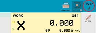
1.2 CNC screen theme
Theme of CNC screen pages
Possible choice from:
• Светлая
• Темная
CNC restart required to apply the setting
Quick theme change is possible via the button in the upper left corner of the CNC screen:
1.3 Full screen window
Setting for automatic expansion of the CNC window to full screen when the CNC starts.
Possible choice from:
• Не раскрывать - start in a normal window
• Полный экран - system startup in full screen
CNC restart required to apply the setting
1.4 Screen scale (Linux)
Applied screen scale (Linux only).
On some Linux distributions, it is not yet possible to determine the screen resolution scaling settings automatically
As a result, the display on the screen may be either very small or very large.
This setting is needed to eliminate this
Possible choice from:
• 0.5х/0.75х/1.0х/1.25х/1.5х/1.75х/2.0х/
CNC restart required to apply the setting
1.5 Toolpath drawing
Method of drawing the passed/not passed tool path.
Possible choice from:
• Выполненное затемнять - Only the uncompleted track will be displayed
• Выполненное выделять - Only the completed track will be displayed
CNC restart required to apply the setting
1.6 Show G0/G28/G30 on the trajectory
Show G0/G28/G30 commands on the trajectory.
Possible choice from:
• Показывать G0/G28/G30 - The track and idle movements will be displayed
• Не показывать G0/G28/G30 - Only the processing track without idle movements will be displayed
CNC restart required to apply the setting
1.7 Show table on the trajectory
Automatically show the table on the trajectory.
Otherwise, the table display is turned on manually by a button in the trajectory display window.
To assess the positive placement of the part on the machine and check the correctness of the G54-G59 task.
1.8 Table size by X and Y
Table size by X and Y. Specified in mm.
Enter the real size of your machine table in this field.
1.9 Table offset from 0 by X,Y,Z
Table offset from 0 by X,Y,Z.
The center of the table (from which the offset is set) is located strictly in the center of the table, specified by the 'Table Size' parameter
The reference point for the table offset is machine zero.
Specified in mm.
1.10 Show chuck on the trajectory
Automatically show the chuck on the trajectory.
Otherwise, the chuck display is turned on manually by a button in the trajectory display window.
To assess the positive placement of the part on the machine and check the correctness of the G54-G59 task.
1.11 Chuck size D, H, Axis
Chuck size:
D - chuck diameter, Specified in mm.
H - chuck depth, Specified in mm.
Axis - chuck orientation along the axes, possible values: A,-A,B,-B,C,-C
1.12 Chuck offset from 0 by X,Y,Z
Chuck offset from 0 by X,Y,Z.
The center of the chuck (from which the offset is set) is located on the front cut of the chuck in the center of rotation
The reference point for the chuck offset is machine zero.
Specified in mm.
2. Common CNC settings
2.1 Machine model name
Machine model name.
Used when naming the parameter archiving file.
2.2 G-code file encoding
Specifying the encoding of NC files containing G-code.
Used when reading and writing NC files.
Possible choice from:
• CodePage 866 - start in a normal window
• CodePage 1251 - system startup in full screen
• UTF8 - system startup in full screen
2.3 PLC section launch frequency
Setting the PLC section launch frequency
In the PCL, inputs-outputs, control panel buttons are read, and the electrical automation of the machine is calculated
A high speed is not required here
Attention!
Probe processing/G31 and axis limit switch processing (for which fast processing is highly desirable) are NOT PERFORMED in this section!
Default value 30 ms
2.4 Size of the buffer of calculated points
Size of the buffer of calculated points for transfer to the servo driver.
In case of communication failure with the servo driver controller - allows the CNC to try to establish communication with the controller during this time.
If communication is restored within the specified time, the CNC will continue to work.
Otherwise, an emergency stop of the servomotors will occur
Set automatically when specifying the controller and usually does not need to be changed
(Generally, it should be closed for modification)
Default is 2s
2.5 Maximum G2/3 program error
In the NC program, the coordinates of the center of the arc interpolation for G2/3 are always transmitted with some error in relation to the initial or final points of the arc + radius - due to the limitation of the resolution of coordinate transmission in the NC program (usually - 3/4 digits after the dot).
The CNC calculates the coordinates of the initial and final points for each G2/3 command based on the coordinates of the center and radius and compares them with the initial and final points from the NC program.
If the difference is greater than the number specified in this parameter, an error will be generated
Otherwise, the CNC will slightly "move" the center of the arc to ensure the "continuity" of the processing path.
2.6 Max. mismatch for G61
Setting the maximum mismatch when smoothing the trajectory for G61
For G61 (finishing), the CNC will round the trajectory so that the distance of the resulting trajectory from the trajectory from the NC program - would not be greater than the value specified in this parameter
This is necessary to optimize the movement of the tool.
• When decreasing the value:
There will be more deceleration "in the corners".
As a result, the processing time will increase, but the processing accuracy will also increase.
• When increasing the value:
The tool will pass "in the corners" at a higher speed.
As a result, the processing time will decrease, but the processing accuracy will also decrease.
This value can be temporarily set to another value using the NC program command G61 PX.XXX
Default value 0.01mm
2.7 Max. mismatch for G64
Setting the maximum mismatch when smoothing the trajectory for G64
For G64 (roughing), the CNC will round the trajectory so that the distance of the resulting trajectory from the trajectory from the NC program - would not be greater than the value specified in this parameter
This is necessary to optimize the movement of the tool.
• When decreasing the value:
There will be more deceleration "in the corners".
As a result, the processing time will increase, but the processing accuracy will also increase.
• When increasing the value:
The tool will pass "in the corners" at a higher speed.
As a result, the processing time will decrease, but the processing accuracy will also decrease.
The value can be set many times greater than for G64,
but do not exceed the tolerance for roughing (we recommend setting half of the roughing tolerance.)
It should also be taken into account that reducing the feed rate during processing reduces the tool's operating time (it becomes dull) (at low feeds, the tool stops cutting the material "per tooth" - and starts "grinding" it)
So a small value (due to a very small feed in the corners) is very harmful to the tool
This value can be temporarily set to another value using the NC program command G64 PX.XXX
Default value 0.1mm
2.8 Max. mismatch for G00
Setting the maximum mismatch when smoothing the trajectory for the G00 command
The same as for G61/64 only for idle movements
When installing, you need to be guided by the logic of the tool movement so that when smoothing the corners, there is no collision with the workpiece.
Default value 1.0mm
2.9 S acceleration profile
Setting the S acceleration profile during acceleration and deceleration
Specified in milliseconds (ms)
Allows you to smooth out jerks when starting acceleration or deceleration - making the machine run smoother.
As a disadvantage – the processing time increases
Default value - 50ms
2.10 Include tool radius in G41/42
Setting to include the tool radius in G41/42
Possible choice from:
• Включать радиус инструмента
The tool radius will be included in the correction value for the cutting tool on the left/right
This setting is usually used to compensate for tool wear.
Advantages - The track in the NC program does not depend on the tool used.
That is, you can select a tool of a different diameter and the track will be calculated correctly.
Disadvantages - if the tool radius in the CNC table and the real tool do not match, the track will be incorrect.
• Исключить радиус инструмента
The tool radius will not be included in the correction value for the cutting tool on the left/right
This setting is used for ACCURATE selection of the trajectory (often for selecting a seat for a bearing)
Disadvantages - The track in the NC program strictly depends on the tool used.
Default value - "Include tool radius"
• ATTENTION! - The value must strictly correspond to a similar value in your CAM system
2.11 Correct G0 feed from the handwheel
Corrector setting for G0 feed
When adjusting the feed rate - The feed rate for G1/2/3/31 commands will always be adjusted
For the G0 command, a setting is possible
Possible choice from:
• Корректировать G0. Both G1/2/3/31 and G0 will be adjusted simultaneously
• Не корректировать G0. Only G1/2/3/31 will be adjusted. The feed rate for G0 is always maximum
Default value - "Correct G0"
2.12 Translate XYZ.. axes to UVW.. in the 2nd channel
Possible choice from:
• Транслировать
When working with NC in the second channel, when transmitting the names of the XYZABC axes, they will be automatically converted to the names of the axes (UVW..) in the second channel
At the same time, it is possible to transmit the names of the UVW... axes in the NC program
• Не транслировать.
When working with NC in the second channel, when transmitting the names of the XYZABC axes, an error will be generated
Transmission of the names of the axes in the NC program only for UVW...
Default value - "Translate"
3. EtherCat settings
3.1 Servo cycle launch frequency
Setting the servo cycle launch frequency
The frequency - with which coordinates are sent to the servo drives
Also in this cycle, probe processing/G31 and axis limit switch processing occur.
Attention!
This value is entirely determined by the capabilities of the controller used
Set automatically when specifying the controller.
Change strictly according to the controller instructions
3.2 EtherCat network interface name
Specifying the name of the network interface to which EtherCat devices are connected.
Communication with servo drivers will be carried out through this interface (network card/output)
Depending on the controller, this may be either a local network interface (network card/output) or on a remote PC or controller.
Attention! - Must be specified!
3.3 Driver type: EtherCat/Other
Driver type: EtherCat / Other
Launching the EtherCat master: locally or on a remote PC via SSH.
• Обучающий режим
The driver does not start.
Work is possible in training mode.
This mode is also suitable for simulating NC programs on a machine for CAM systems.
• EtherCat: Текущий ПК
The EtherCat master driver will start on the local PC
• EtherCat: Удаленный ПК
The EtherCat master driver will start on the remote machine.
First, a connection will be established with it via SSH.
Next, the driver will be copied and launched on the dedicated PC
Remote PC - only a PC on Linux with an X64 or Arm64 processor
3.4 Remote PC: IP address
An SSH connection will be established with the remote PC via this IP.
And UDP packets will be exchanged with the driver via this IP.
3.5 Remote PC: login and password
Login and password to connect to the remote PC via SSH.
On the dedicated PC, this login and password must have the right to the SUDO command (i.e. PC administrator rights).
3.6 List of CPU cores for RT
List of CPU core numbers to launch the RT servo cycle stream..
The servo cycle in the driver will be launched on the selected core/cores.
The list includes both individual cores and a pair of cores.
3.7 Delay after turning on the machine
Delay after turning on the machine's power supply - to load EtherCat devices
This setting will be applied after the power supply is turned on until the moment the presence of EtherCat devices is read.
It is needed so that EtherCat devices have time to load and start responding on the bus.
Otherwise, devices that load slowly may be skipped during initialization.
4. 'G' command settings
List of G-commands predefined by the CNC system, as well as G-commands added by users.:
Predefined CNC commands cannot be changed or configured.
They are provided for reference and to search for "windows" of free G-command numbers.
The user can add their own G-commands.
Fields. filled in for each G-Command:
4.1 'G' command identifier
Identifier/Name of the 'G' command.
Stock, Format 'G##0.##'
The identifier must be strictly unique in the table.
4.2 Command file
Name of the file that implements the execution of the command.
Without specifying the path, with the file extension.
The file itself must be located in the "Cycle" directory of the directory where JupiterCNC is installed.
4.3 Modal
Attribute - Whether the command is modal.
For reference - does not affect anything.
4.4 "Group 'G' commands
Names of other 'G' commands - which the command belongs to. .
For reference - does not affect anything.
4.5 'G' command description
Brief description of the command implementation.
For reference - does not affect anything.
5. M Command Settings
List of predefined M-commands by the CNC system, as well as user-added M-commands:
Predefined CNC commands cannot be changed or configured.
They are provided for reference and to find "windows" of free M-command numbers.
The user can add their own M-commands.
Fields to be filled in for each M-Command:
5.1 'M' Command Identifier
Identifier/Name of the 'M' command.
String, Format 'M##0.##'
The identifier must be strictly unique in the table.
5.2 Command File
Name of the file that implements the execution of the command.
Without specifying the path, with the file extension.
The file itself must be located in the "Cycle" directory of the directory where JupiterCNC is installed.
If the file name is not specified, the command must be executed in the PLC.
5.3 Modal
Attribute - Whether the command is modal.
For reference - does not affect anything.
5.4 "M Command Group
Names of other 'M' commands - which the command belongs to. .
For reference - does not affect anything.
5.5 'M' Command Description
Brief description of the command implementation.
For reference - does not affect anything.
6. MODBUS Devices
In this section, you can describe and configure connected devices via the MODBUS protocol'
Default communication parameters: 9600 Band (can be changed), 8 Data bits, None Parity, 1 Stop Bit。
6.1 Device Name
Brief device name.
For reference - does not affect anything.
6.2 MODBUS Device Number
Device number according to the MODBUS protocol.
Must be unique for each device for each port.
This number must be written in the device.
• ATTENTION!
This parameter must be specified.
6.3 RS485/422 Port
Name of the port for communication via MODBUS.
Selected strictly from the proposed list.
The list may contain both local ports (Local).
As well as remote ports (on the machine where the controller is running).
The same port can be selected for different devices.
• ATTENTION!
This parameter must be specified.
6.4 Exchange Rate
Port exchange rate for communication via MODBUS.
Selected strictly from the proposed list.
The same port can be selected for different devices.
For the same port, you must specify strictly the same speed.
• ATTENTION!
This parameter must be specified.
As a rule, the speed is set to 9600 Band by default in all devices.
6.5 Device Purpose in PLC
Selection of a specific predefined purpose of MODBUS devices.
Allows the PLC code to understand exactly which device to control.
In the PLC, the device assignment is determined by creating a "PlcServoDriver" object
The field is not required.
If the field is not filled in, then in the PLC you need to implement the code for controlling this device (if it is not just an In/Out board, but for example a ServoDriver)..
6.6 Predefined Setting from PLC
Selection of a specific setting of MODBUS registers and binding of PLC Inputs/Outputs.
In fact, this is the selection of a predefined communication protocol with a MODBUS device, described in the PLC in the "ProtocolServoDriver" object.
The field is not required.
If the field is not filled in, then you need to manually prescribe the MODBUS control registers (below).
- and manually bind MODBUS registers to PLC inputs/outputs.
- and in the PLC implement the code for controlling this device (if it is not just an In/Out board, but for example a ServoDriver).
6.7 Number of pulses per revolution / Number of motor poles C
For the standard implementation of the servo driver control code in the PLC
must know how many pulses/steps the MODBUS ServjDriver device is programmed for.
For other devices, you can not fill it in.
Table of MODBUS register addresses:
6.1 MODBUS Device Command
Setting the MODBUS register type:
• Error number - Register - from which spindle errors are read
• Error reset - Register - to which you need to write the error reset command
• Stop motor - Register - to which you need to write the spindle stop command
• Start motor - Register - to which you need to write the spindle start command
• Reverse motor - Register - to which you need to write the spindle reverse start command
• Set motor speed - Register - to which you need to write the motor speed value
• Get motor speed - Register - from which you need to read the current motor speed value
• Get motor power - Register - from which you need to read the current motor power value
• Read discrete inputs 1/2 - Register - from which you need to read the value of discrete inputs
• Read analog input 1/2 - Register - from which you need to read the value of analog inputs
• Write discrete outputs 1/2 - Register - to which you need to write the value of discrete outputs
• Write analog output 1/2 - Register - to which you need to write the value of analog outputs
6.2 MODBUS Function
Method - with the use of which the MODBUS register is read/written
See the MODBUS protocol documentation
6.3 MODBUS Register
MODBUS register (not to be confused with the MODBUS Address number)
Specified in hexadecimal.
In the documentation, it is also usually specified in hexadecimal.
If the documentation specifies the "Address" MODBUS then:
Calculating the register number from the "Address" MODBUS:
• Discrete output ports:
[MODBUS Ares : 00001-09999] - 00001 = [MODBUS Register: x0000 to x270E]
• Discrete input ports:
[MODBUS Ares : 10001-19999] - 10001 = [MODBUS Register: x0000 to x270E]
• Analog input ports:
[MODBUS Ares : 30001-39999] - 30001 = [MODBUS Register: x0000 to x270E]
• Analog output ports:
[MODBUS Ares : 40001-49999] - 40001 = [MODBUS Register: x0000 to x270E]
6.4 Multiplier/Value/Quantity
Setting the MODBUS register type:
• Error number - not available
• Error reset - Value - to which you need to write the command to reset the error
• Stop motor - Value - to which you need to write the command to stop the spindle
• Start motor - Value - to which you need to write the command to start the spindle
• Reverse motor - Value - to which you need to write the command to reverse the spindle
• Set motor speed - Multiplier - by which you need to multiply the desired speed - to write to the register
• Get motor speed - Multiplier - by which you need to multiply the read value to get the current motor speed
• Get motor power - Multiplier - by which you need to multiply the read value to get the current motor power
• Read discrete inputs 1/2 - Number of discrete ports (bite)
• Read analog input 1/2 - Number of analog ports
• Write discrete outputs 1/2 - Number of discrete ports (bite)
• Write analog output 1/2 - Number of analog ports
7. Machine Axis Settings
7.1 Axis Purpose
Axis assignment on the machine.
• Linear X/Y/Z Linear axis X/Y/Z in the 1st or 2nd channel.
• Rotation X/Y/Z Axis of rotation along the X/Y/Z axis (ABC axes) in the 1st or 2nd channel.
• Spindle Spindle (without position control) in the 1st or 2nd channel.
• Rot.Z + Spin. X Spindle with the ability to work in position mode in the 1st or 2nd channel.
• Subordinate X/Y/Z Subordinate portal axis in the 1st or 2nd channel.
• Non-interpolated Working with the axis is possible only from the PLC in JOG mode.
7.2 Axis Channel
Channel in which the axis operates.
7.3 Position on the CNC screen
Position of information on the CNC screen in special panels.
Specified as a line number, as well as the position in the line.
Possible:
• or the axis information occupies the entire line on the panel
• or the axis information occupies the left or right area of the panel
7.4 Feed Rate G1
Maximum feed rate during processing (G1/2/3).
Specified in mm/min or deg/min
Determined by the capabilities of the servo driver, motor and machine mechanics
7.5 Feed Rate G0
Maximum feed rate during idle movements (G0).
Specified in mm/min or deg/min
Determined by the capabilities of the servo driver, motor and machine mechanics
7.6 Feed Rate When Homing
Feed rate for searching limit switches when homing.
Specified in mm/min or deg/min
7.7 Acceleration G1
Axis movement acceleration during processing (G1/2/3).
Specified in mm/sec² or deg/sec²
7.8 Acceleration G0
Axis movement acceleration during idle movements (G0).
Specified in mm/sec² or deg/sec²
7.9 Homing Type
Determines whether homing is required or not.
• Forbidden - There are no limit switches on the axis, zero memorization occurs in a multi-turn absolute encoder
• Required - There are limit switches on the axis, when the machine is turned on, the homing procedure is mandatory
• No - There are limit switches on the axis, zero memorization occurs in a multi-turn absolute encoder, when the machine is turned on, the homing procedure is NOT! mandatory
7.10 Homing Method
Determines the homing mechanisms.
• Limit switch + 0 mark - First, a search is made for the limit switch on the axis (connected to I/O), then in the opposite direction a search for the Z mark on the encoder
• By limit switch - Only a search is made for the limit switch on the axis
• Limit switch (in drive) + 0 mark - First, a search is made for the limit switch on the axis (Connected to the servo driver), then in the opposite direction a search for the Z mark on the encoder
In this case, it is required that the limit switch input is configured in the servo driver (see the servo driver instructions)
7.11 Homing Direction
Determines in which direction the axis will start moving when searching for the axis limit switch.
• Positive - Towards the + Axis
• Negative - Towards the – Axis
7.12 Position Limit Switches
Determines whether to use travel limit switches on the axes.
• Use limit switches - if the axis hits the limit switch, an error will be generated
• Do not use limit switches. - Hitting the axis on the limit switch will be ignored
(the limit switch will only be used for "Homing")
7.13 Pulses per 1 rev.
Number of lines/Steps per 1 revolution of the servo motor (PUU)
Often corresponds to the encoder resolution.
If the electronic gearbox settings are set in the servo driver, then this value must correspond to PUU (See the servo driver instructions)
7.14 Movement per 1 rev.
Movement per 1 revolution of the servo motor, mm/rev or °/rev
7.15 Following Error Max.
Following error at maximum speed, mm
At intermediate speeds, linear interpolation will be performed between 6.16 and 6.17
7.16 Method of 'Spinning' the axis of rotation
The method by which the calculation of 'Spinning' the axes of rotation will be performed
• Rotate to the full angle - by the command G0 A/B/C#.### the axis will rotate to the full angle specified in the command.
For example, if the angle of axis A=920 - then by the command G0 A0 the axis will rotate by -920 degrees and the value will become equal to 0 deg.
• No more than 1 rev. to the nearest - by the command G0 A/B/C#.### the axis will rotate to the minimum angle - the remainder of the division by 360 and reset to the specified value.
For example, if the angle of axis A=920 - then by the command G0 A0 the axis will rotate by +160 degrees and the value will become equal to 0 deg.
• No more than 1 rev. in the direction - by the command G0 A/B/C#.### the axis will rotate to the angle - the remainder of the division by 360 and reset to the specified value.
For example, if the angle of axis A=920 - then by the command G0 A0 the axis will rotate by -200 degrees and the value will become equal to 0 deg.
7.17 Offset of the slave axis
Offset of the slave axis - relative to the master axis
Applied by the CNC after both (Main and slave) axes reach zero:
- The slave axis will shift by this value after homing
Do not set a value greater than 5 mm - the portal may twist and break
If homing by Z-mark of the drive is used, then you need to:
• Or set both motor shafts so that the Z-marks are on both drives approximately at the same distance from the limit switch.
• Or immediately prescribe the difference between the Z-marks of the drive - so that the portal does not twist.
We recommend first disconnecting the drives from the ballscrew, performing homing by limit switches and Z-mark (touching the limit switch with a screwdriver),
And only then tighten the coupling on the ballscrew on both drives.
Then the Z-marks on both drives will be at the same distance from the limit switch.
7.18 TCP: What does the axis rotate
What does this axis rotate? Table (Part) or spindle.
This is important for TCP - the coordinates of the cutting point are calculated differently.
7.19 TCP: Order of rotation axes
The serial number of the axis of rotation from the machine frame.
This is important for TCP - the order of the axes during rotation is important.
For each axis, its path to the machine frame is built.
And depending on this, the coordinates of the joint are calculated.
For the Table and for the Spindle there should not be axes with the same serial number from the frame
7.20 TCP: Offsets of rotation axes
Offset of the axis of rotation from the second axis or the spindle axis.
This is important for TCP - the offset of the axes leads to a shift in the calculated coordinates during rotation.
For the axes of rotation of the spindle:
- For the first axis, the offset from the center of rotation of the axis to the axis of rotation of the Spindle tool is set. X or Y
- For the second axis, the offset from the center of rotation of the axis to the axis of rotation of the Spindle tool is set. X or Y and Z
For the axes of rotation of the spindle:
- For the First axis (with two axes of rotation), the offset from the center of rotation of the first axis to the center of rotation of the second axis is set.
- For the second axis (with two axes of rotation) or for the first axis (with one axis of rotation), the offset is not set
7.21 TCP: Ballscrew backlash compensation
The value of the ballscrew backlash in this axis.
The CNC will try to select the backlash for different directions of movement and alternating accelerations.
0 - Disabled.
It is necessary to take into account the fact that it is impossible to predict in some cases in which direction the axis will deviate due to backlash.
8. Coordinates of CNC reference points
Various coordinates - used when working with CNC
• G28 - Working position
• G53.1 - Zero machine coordinates
• G53.2 - Negative software limit of axis travel
• G53.3 - Positive software limit of axis travel
• G30.1 - Position before measuring the length of tool 1
• G30.2 - Coordinates of the tool measurement sensor 1
• G30.3 - Position before measuring the parameters of tool 2
• G30.4 - Coordinates of the tool measurement sensor 2
• G30.5 - Position before manual tool change
• G30.6 - Position before automatic tool change
• G30.7-G30.9 - User reference points
9. Binding Inputs-Outputs to PLC
Binding Inputs-outputs (declared in the PLC) to specific IO devices
The list of devices will show MODBUS MODBUS, EtherCat MODBUS, HID devices
Also, the list may contain EtherCat-ServoDriver devices - in which the I/O registers are specified in the settings
I/O binding fields:
9.1 Input-output value
Current input-output value
Shown for reference
9.2 Inverting the input-output
Inverting the input-output value after reading and before output.
Only for discrete inputs-outputs
9.3 Input-output assignment
Binding the input/output to the Inputs-outputs declared in the PLC
The list of input-output assignments can be changed in the PLC.
The list of PLC Inputs-outputs is grouped by groups of Inputs-outputs for convenience.
10. Machine geometry correction
Settings that allow you to programmatically (mathematically) change the geometry of the machine
Can be used for:
• Correction of axis perpendicularity
• Correction of ballscrew nonlinearity
• Correction of guide nonlinearity (curvature)
• Geometry correction from temperature (for example, spindle)
Correction for the slope of the part is not implemented!!!
5 correction channels are implemented, the input parameters for which are:
• Machine position on the X axis
• Machine position on the Y axis
• Machine position on the Z axis
• Output of a numerical value from PLC #1
• Output of a numerical value from PLC #2
It should be borne in mind that the correction is pre-calculated by the trajectory planner,
And it cannot be changed dynamically from the PLC
In each channel, several values of the input parameter and correction values for them are set for three XYZ axes
If the Input parameter is between two values, then linear interpolation is applied between the two adjacent values.
If the Input parameter is Greater or Less than the extreme values, then the adjacent value is applied.
Specify small values in the correction values.
The system is not designed to correct large values of nonlinearity.
10.1 Correction description
The predefined name of the channel is indicated - by which you can understand what input parameter is transmitted to the channel.
10.2 Channel in which geometry correction occurs
The first channel by default.
For two-channel machines, there are two channels for each axis - 1 and 2.
10.3 Input parameter value
For a line, a point on the input axis is indicated.
10.4 Correction by X
The correction value applied to the X axis is indicated.
10.5 Correction by Y
The correction value applied to the Y axis is indicated.
10.5 Correction by Z
The correction value applied to the Z axis is indicated.